This is the locomotive diagram drawing from archives of the Soo Line historical society. It was published as supporting material in an article. It was most helpful in the tender construction as it gives a number of important dimensions, in particular the tank.
Symmetry is the key to laying out the side of the tender. I learned about the advantages of symmetry when learning how to draw with CAD, if you could define symmetries you only need to draw a portion of the object and then fold it to get the whole image. In the case of the tender side I identified a symmetry about the center of the rear tank wall. I folder a paper and then drew half the tank carefully marking the locations of the fold lines for the bunker return, front, side and rear. I then cut out the outline. The above photo shows the folded template.

I used .005 brass sheet for the sides of the tender tank. I sliced off a piece just a little wider than the template. I sprayed it black with the intention of marking the outline of the template on the painted surface. To hold the template in position while tracing I choose to use rubber cement to bond the template to the metal. Since it was bonded I decided to skip the tracing and I just cut close to the template with shears, filing to the finished edge.

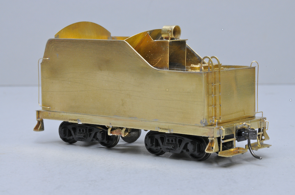
Here is how the sides looked after they were cut out and before folding. The next step was to fold up the sides. This is tricky as you need to fold both sides in the same sequence and from the same direction to keep the whole assembly the same size. I folded from the front corners backward toward the rear corner. I tightly clamped a straight edge against the surface of the sheet aligned on the fold lines and then bent the metal up. Working slowly and carefully is the name of the game. This is what the folded up tank appeared like when I was done.




 It has been well over a year since I have done any major projects on the NAPM layout, the last being the mountain project, so it is time to get going on something new. The city industrial area has not had any serious efforts made to it in several years and there was a great desire to get the wharf area completed as one of the club members is just about done with a model of a tug to complement the car float. Unfortunately, the tug will be on the aisle edge of the layout and there was no plan to do anything with the area behind. If the scenery was done on the front it would have been subject to damage when the scenery was done behind it, it became necessary to come up with a plan for the background.
 My solution is to cover the area in large structures all placed at angles to hide the track configuration and produce visual interest. The views from various directions need to make the tracks look as though they disappear behind buildings. in essance we are creating a short tunnel through a ridge of buildings. The following photos show my initial plans.


