Wednesday March 27, 2013
I have chosen to build a deck girder 56 foot turntable with stone rubble pit walls. The first step is to layout a base and a circular pit filler.
I laid out two nine inch squares and drew diagonals through there corners to mark the centers. The right square will become the base. On the left square I used a compass to draw a 56 foot circle which will be the pit filler. I then used a saber saw to cut out the circle and the base. When done I squared up the edge of the circle with a sanding block.
I am going to use the same mold to create the rubble pit wall as was used to make the ash pit. This mold produces an eight foot wall which will work out well for this project.
In this view you see that I have placed my pit filler in a vise. The filler is only 1/2 inch thick and the mold is 1 1/2 inches wide. To support the mold I taped a strip of cardboard to the filler, it is centered on the pit filler edge. Next I mixed up a batch of hyrocal and filled the mold. When the mixture became self supporting (not so fluid as to run out of the mold but not set to the point of cracking or breaking) I laid the mold over the cardboard.
I then clamped the end edges of the mold to the cardboard and allowed the hyrodcal to set completely.
Thursday March 28, 2013
Here are the completed wall segments. Unfortunately the ends of each segment did not follow the curve. I should have stapled the cardboard to the disk and not relied on tape. At least two thirds of each casting is good so I should be able to get the pit wall completed with the four castings.
I was listening to the Model Railcast show today, episode 179a, and there was a discussion on turntables. It was mentioned that Bob Hayden had used a stereo jack to create a center pivot for a turntable. I have a few jacks and sockets around so I think I will give it a try. The jack will not reverse the polarity of the bridge rails but it will provide a resistive pivot. Once the rails are aligned the bridge should remain in place while the locomotive moves on and off. I can take care of the polarity electronically.
I used a 1 1/2" Forstner bit to recess the area of disk for the jack socket. I applied a small amount of five minute epoxy to both sides of the disk around the hole.
I also cut a 1 1/2" hole through the base plate. The large diameter of the hole gives clearance for the jack and provides room to do any soldering.
Friday March 29, 2013
I bonded the pit disk to the base plate with carpenters glue aligning the large holes. When dry I inserted the jack into the small hole and snugged down the hex nut to
finger tight. Note that the jack end is flush with the nut.
I used a 1/4" square wood strip (make sure it is not bowed) and verified that the top of the jack was even. This can be determined by inspecting the gap between the stick and the disk surface, it should be the same on both sides. Rotate the stick slightly and recheck. Adjust the jack as needed and when the gap is the same through 360 degrees bond the jack to the disk with gap filling CA. Take your time with this and be fussy, the performance of the table is effected by the care taken here.
I also applied CA to the back around the jack as well.
The center of the pit will have a foundation made of rubble. I cast a .060 thick part from my wall pattern. To control the thickness I used a couple of .060 styrene strips and leveled out the hydrocal between them.
I cut two four foot strips from .040 styrene sheet for the side stringers. I bonded the ends with a little MEK and aligned one side. The clamps keep the edge aligned. I sanded the edge to make sure they were flush. I then flipped the clamps and repeated the process on the other edge.
The side stringers are spaced five feet apart. I subtracted the thickness of the side and cut out a base from the .040 styrene sheet.
A center line is struck across all three pieces. All dimensions are taken from the center line. The center strip is the base.
This is the base. Shown are the dimensions from center to the angle section and the end. Also indicated are the dimensions to the center of the hole for the jack.
This is a close up of the end of the side girder. The taper starts 16 feet from the center.
I used a washer from the jack as a guide in laying out the hole for the plug. I traced around the interior opening and then used a slightly undersized drill to create the opening. I then used a round file to increase the size of the opening such that the plug could be threaded into the hole. This is slow work as you do not want to remove to much material.
Here is the result with the plug screwed through the base strip. The area below the threads is narrower than the threads so there is some room to shift the base slightly to aid in alignment of the bridge.
Here are all of the pieces cut out and ready of assembly.
Next I assembled the sides to the base pieces.
Using the cut off base material I created cross braces and bonded them in place. They are spaced at five foot intervals.
Here is what the bridge looks like when mounted into the jack. At This point I verified the tracking of the bridge and was disappointed to see that it was wobbling up and down. To correct for this I reduced the pressure that was being applied to the plug by the spring contacts on the jack. I was able to get it to track smoothly. All right!! Thought that I might have to start all over.
Saturday March 30, 2013
I allowed the hydrocal center pier casting to set over night. I sanded it to a uniform thickness (approx. .050") and cut it to size, a scale six feet on a side. I then traced around the outside of the washer after centering it on the casting. I used a 9/32 drill and made a hole in the casting and then carefully filed out the opening to match the scribed line.
I then glued the casting in place with Walthers Goo.
I used scale 1x12 styrene strip to form the edges of the bridge. I start at one end and centered the material on the side plate. I did the same on the opposite end.
Next cut the end pieces flush with the bridge top and bottom on both ends. Apply another 1x12 strip on the top between the ends. Align the strip with the outside edge of the end flange and glue in place. As you can see I did this with the bridge upside down. You can use a straight edge to make sure that the strip is even and has the same overhang along the side plate.
To add the bottom flange I use the base of my square as a back stop. I align the edge of the top flange against the square bottom. I position the bottom flange against the square base and bond the styrene 1x12 strip. I work my way along the the bridge bottom aligning and applying glue.
I use the same process for the diagonals and end piece.
This photo (view large version) shows the dimensions for the placement of the vertical stiffeners. The center pair are located two feet off center and are shown here as four feet apart.
The two center stiffeners are created from .010 x .125 styrene strip. The rest are made from .010 x.060 strip material. As can be seen the center two are centered on the marks. Stiffeners on the right are positioned to the left of the mark, stiffeners on the right are positioned to the left.
I then added .020 x .040 styrene strips. Again note the center left and right placement.
I thought that the .020 material looked a little large. On the opposite side I used .015 x .040 strip material for the vertical members. I think that they look a little better, I'll keep that in mind when I do another girder in the future.
I applied Micro Mark rivet decals to the plates. I primed the surfaces which were to receive decals with Future floor wax. I used Solvaset to set the decals.
Monday April 1, 2013
Mechanical issues. After completing the bridge, installing the plug and testing it became obvious that the bridge still wobbled up and down even with the reduced pressure of the jack contacts. If I reduce the pressure to zero (no wobble) then the table free wheels making positioning with the approach tracks difficult. To solve this problem it seemed that some type of end support would be needed on each end of the bridge. It would also need to be adjustable. I decided to add a 1-72 hex head bolt to the ends of the bridge. The plan is to have it slide on the pit rail and stabilize the wobble.
I measured back one scale foot from the end of the bridge. Next I marked 1mm toward the center of the bridge. I cut two seven scale foot .100 styrene I beams gluing one in place at my marks. Next I cut a .100 x .125 styrene strip to the width of the bridge and bonded it next to the I beam.
I then added the second I beam. After marking the center of the .100 x .125 strip I drilled and tapped for a 1-72 bolt. I repeated this on the other end as well.
I reassembled the plug and centered it in the bridge. I visually double checked that it was centered over the pit base (there were slight variations in the cutting of the pit base). Using the bolt center as a reference I marked the disk ever 3/8" around the perimeter. When done I verified that the opposite bolt would follow this line. The bolt will be sliding on code 55 rail so this rail center line needs to be precise.
The jack creates a hole in the center of the pit so it was not possible to use a compass to draw the rail center line.
I created a disk from cardboard to used as an edge for drawing the pit rail center line. The distance between bold heads was 190 mm so I set up my compass to draw a 95 mm radius. To aid in aligning the pit rail ties (two feet in length) I also inscribed another line with a radius 3.5 mm less than the rail center line.
I cut out the disk and positioned it to aline with the dashed marks made previously. I then traced around the circle.
When done I re cut the disk to the tie edge line. Position it such that there is an equal space within the rail center line and trace another line.
I used scale 8x8 bridge ties cut to a two foot length to support the pit rail. It required about 150 tie segments. I applied glue to each tie aligning each end with the inner circle. The ties need to point toward the pit center.
To aid in alignment I created a plug from 1/4" square wood. Bottom rounded to fit in jack. I added a brass wire centered in the side of the plug. By rotating the wire over each tie you can align the tie to point toward the center.
I used a paper punch to create four disks from .040 styrene sheet. Notch the corner of the disk as shown.
Apply the disk between the I beams on the end. These will simulate the wheels that ride on the ring rail. Since I am going to be dragging brass bolts over the ring rail I might as well pick up my turntable rail power from them. This is a change in plan as I had originally planned on using an auto reverser and getting my power from the jack plug. I drilled a hole in the bridge base to accommodate a feed wire.
This is a general overview with all of the ties in place.
I curved a piece of code 55 rail to match the center line drawn on the pit base. This is a trial and error process but with patience you will be able to match up exactly.
I butt soldered the rail ends to make sure that I had uniform curvature through the joint.
I stained the ties with ink washes. When dry I proceeded to spike down the ring rail at the point indicated with the pencil lines. The red marked area is where gaps will be cut to create the dead rail section. You need this to prevent a short when the bolt head passes over the gap between powered ring rails. I placed a pair of spikes at a 90 degree spacing around the ring. Check the alignment using the bridge, the bolt heads needs to sit on the rail all around the ring. Do this frequently. I then spiked down the two quadrants which do not have the dead section. Lastly I spiked down the quadrants with the dead sections.
Tuesday April2, 2013
This photo shows how I spiked the area around the dead section. Note that the rail on both side of the gap are spiked. I also CA'd the rail to the ties at all spike locations as well as the entire base of the dead section. I used a razor saw to cut in the gaps.
A small piece of .015 x .040 styrene strip was glued into the gap. The tops were cut flush and filed smooth.
The decking is built up from scale 8 x 8 wood. The long ties are 14 feet and the short ties are 10 feet in length. There is an unusual stagger arrangement to the ties. Long ties have a three foot overhang on one side. To aid in placing the ties I created a jig which has a tab three feet long and is square to the side. The jig in the photo shows a tab which was not square to the side of the jig. I determined the center of the bridge and worked out toward the end. The first tie was place three scale inches from the center. The three foot end of the jig is pressed against the side of the girder, end of tie is aligned and glue is applied. The jig is flipped around and the process is repeated on the other center tie.


The short ties are ten feet long. I added a two foot offset to the other end of the jig and used the same process to place them. I also created a 6" tie spacer by gluing a scale 6x8 to some scrap. The tie pattern looks a little confusing but once you do a few it flows along quickly.
The deck end is created from a scale 8x18. It is tapered back to eight inches the taper starting five feet from the end.
To add the end I created another jig. It is built up from two .030 x .156 strips. The jig is clipped to the side of the end piece and then attached to the bridge. This will create a three inch overhang on the end of the girders.
Here is the completed deck.
The walk ways are built up from scale 2x10 strip wood.
Thursday April 4, 2013
I built up wireing terminals from .010 brass sheet. I drilled clearance holes for the 1-72 bolts, rounded the ends and cut the strip in half. I then soldered on a short length of feed wire.
This was then attached to the end of the bridge. The wire passes up through the ties.
I then adjusted the bolt to slide along the rail top. It is critical that it be in contact with the rail when in position with the approach tracks. This will ensure that power reaches the bridge rails when a locomotive is moving on or off the table.
Friday April 5, 2013
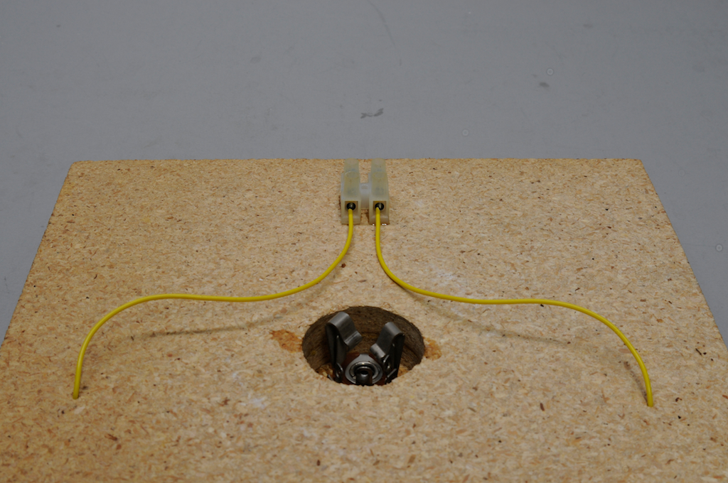
I added feeds to the ring rails. I used yellow feed wire for this. It is my standard color for turnout frogs. The polarity on the rails will be determined when it is installed thus the use of yellow wire. A terminal bock was used to expedite the connection to the power feeds.
Saturday April 6, 2013
I cut and fit the pit walls using my previously marked quadrants. Work slowly at this as you need to align the wall with the bridge. I tried to maintain a six scale inch gap but there are variations in the castings so it is not uniform.
As can be seen in this photo the wall height is slightly below the top of the bridge. It needs to be even with the base of the ties. I used my caliper to determine that I needed to raise the wall sections three millimeters.
I used a scale 10 x 18 as a filler gluing segments along the bottom of the wall. This brought the wall up to the base of the ties.
Sunday April 7, 2013
I primed the castings by spraying with white paint. When dry I applied diluted Polly Scale grays and brown tone paints to the stones. When they were dry I washed them with my Instant Age solution. Again after drying I flowed diluted modeling paste between the stone to represent mortar.
Thursday April 11, 2013
I had to get some clear silicon sealer so progress has been delayed a bit. I added a bead of silicon around the side of the pit and a small amount to the bottom of each wall segment. I then positioned the pieces, adjusting each one to clear the bridge.


No comments:
Post a Comment