Sunday April 14, 2013
We will start with some overviews of the parts that constitute the kit. The bag on the lower left has the end door scribed wood and the bolsters. The package on the right contains a mix of detail parts. Top left is the nylon line used for truss rods, a casting containing door hardware, another casting with the K brake components and lastly some soft brass wire.
Details in the bag. Grab irons, truss rod end bolts, turnbuckles, stamped brass corner brackets, corner steps and needle beam/queen post castings.
Wood components. Roof, floor, end blocks, center sill, running boards and various sizes of color coded strip wood.
Sheathing. Four roof pieces, next row two end walls and two doors and lastly four sides.
Monday April 15, 2013
Lets get started. the first step is to clean up the needle beam/ queen post casting. I noted that on all of the kits one end of the beam casting was a little thicker than the other. I filed the base of the casting to give a uniform thickness. I then filed the opposite surface to remove the parting line and squared up the queen posts. It was also necessary to widen the notches in the end of the queen posts. Upper rough casting, lower cleaned up casting.
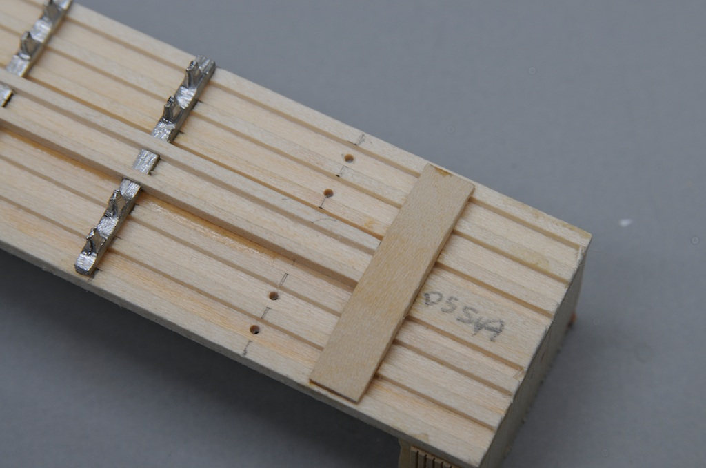
The space over the outside faces of the needle beams is 21mm, the total length of the floor is 117mm. The needle beams should be
48mm from the end of the car, dimension in photo is incorrect. Mark the locations and CA the beams in place.
The center sill needs to be notched to fit over the needle beams. The end of the sill is 20.5mm from the end of the car. Position appropriately and mark the cut locations on the side of the sill. Use a razor saw to cut the notches to depth and use a hobby knife to remove the waste. I used files to bring the notch to the correct depth.
Glue the center sill in place and add the bolsters centering them between the sides. On this model the floor is a little wider than usual so the bolsters do not quite reach the sides.
At this point I added the end blocks. As can be seen they were also a little narrower than the floor. Line up one edge flush with a side and glue the block in place. Make sure it is flush with the end. Clamp an allow to dry. For this wood to wood bond I use carpenters glue. Once dry I added a scrap of 1/32" thick sheet to the edge to extend the block side to the edge.
Tuesday April 16, 2013
Drill four holes 28mm from the end of the car for the nylon truss rods. They should align with the tops of the queen posts. You want to make sure that the wheels will not hit the rods ensures that they will clear. Do this on both ends of the car.
Thread the nylon through the holes. Place a turnbuckle on the line then feed it through the car bottom. Repeat for each set of posts. I snug the line over one queen post. When completed I pull the line up over the second post. This gives nice tight lines.
This is how the lines look on the interior of the floor. On the lower right is the starting knot.
I use a piece of wood as a plug to secure the nylon line in the last hole. I then apply CA to all the holes and across the lines on the interior of the floor. See prior photo.
Part number 1 (on left) and part 2 (brake cylinder) are assembled.
The base is added extending out from under cylinder and flush on the back side. This will allow the cylinder to be attached to the center sill and offset to the side.
This photo shows the cylinder attached to the center sill.
I use Westerfield 18" straight grabs as lever brackets. On the right are the holes for the main lever brackets. On the left is a grab positioned for marking of the second hole. The first hole is centered on the needle beam.
I use part 17 (on right above steps) as the main lever and part 20 (far left) for the secondary lever. Drill a hole (#79) in the end of the secondary lever opposite the cast clevis.
This photo shows how the secondary lever is added to the center sill. Once the lever is glued to the bracket trim the wire passing through the hole.
Wednesday April 17, 2013
This is a close view of the main lever. Note that it passes through the clevis on the brake leaving a small pad to attach the rod that would go to the brake wheel.
Once the levers are secured attach the rod between them. Note that I have drilled holes in the center sill aligned with the truss rod penetrations. There are two holes on the right and one on the left.
Add the rods on the right. The close one would go to the truck and the back would go to the brake wheel.
Now add the rod that attaches to the secondary lever. Note that I crush the end of the wire which attaches to the lever. This gives the appearance of a clevis on the rod.
I add a scale 6x18 spacer block to the bolsters. I cut it a little wider than the center sill. This piece raises the car bringing the floor bottom up to coupler height. When the model is finished this piece can be sanded/shimmed to fine tune the height.
I attach the Kadee arch bar trucks at this time. They will protect the brake rigging during the rest of the build. Always remain vigilant when handling the car as your fingers will always seem to grab the rigging!
Prior to attaching the trucks I glued the roof the the body and clamped it until dry. When aligning the roof make sure the peak is centered on the end block.
Sunday April 21, 2013
Glue segments of the yellow end strip wood across the top of the end matching the bottom to the lower edge of the roof eve. Glue the end wall wood to the end block. As can be seen the width of the scribed wood did not cover the end block. This indicated to me that I should have made the floor narrower to match the end block. On my other kits the floor and end block widths matched. Learning point, make sure that the floor width, end block width and end wall sheathing width are all of the same dimension.
I filled the gap in the end sheathing with small segments of scribed wood. When the glue was dry I cut the peak to shape and sanded the end sheathing flush with the sides.
Add the sheathing to one side. Clamp down until the glue is dry. Cut off the excess end material and sand/scrape flush with the end.
I use lead sheet material to add weight to the car. This amount of lead brings the final car weight up to four and a quarter ounces.
I use Walthers Goo to bond the lead to the floor. I also use Goo to bond each piece of lead to the other. Because of my adjustment to the width of the car it was necessary to add a strip wood filler under the eve.
I then glued the second side sheathing on the car. This photo illustrates the clamping technique.
I tape scrap 1/32" thick wood to the side of the car. I then sand the eve flush with the taped on wood. Do this on both sides.
Glue the doors on the sides, clamping until dry. Then add segments of the light blue strip wood above each door.
Determine the center of the roof. To do this I make a mark fifteen millimeters from each the eve. I then split the difference between the two marks.
Tuesday April 23, 2013
I used my caliper to determine the width of the roof sections, they needed to be cut to 16.75 mm. I bonded them to the roof base aligning them with the ridge line. When dry I sanded the ends to the correct overhang. In this photo you can see that I have marked the positions of the running board supports. I spaced mine two scale feet apart.
Using the red labeled wood I cut 34 twelve inch long pieces and bonded one to each side at the marks. I find it most efficient to do one roof side then back on the other.
When the glue has set completely I sand the running board supports flat. I place some 320 paper on a flat surface, flip the model upside down and draw the car body back and forth. Work slowly and inspect frequently, stopping when a flat surface exists across the supports.
Glue the prefabricated running board to the supports. When dry use a sharp blade to cut off the protruding ends of the supports.
The end doors are cut from the supplied stock. Red labeled wood is used for the lower door rail, green labeled wood for the upper guide.
This model has framing around the door. It is built up from the black labeled strip wood.
At this point all of the wood construction is completed. This model represents a wooden freight car that should appear to have been in service for ten years. To begin the process of painting I use my diluted Dr. Bens Instant Age and Weathered rust to stain the superstructure.
Thursday April 25, 2013
I brush paint the under frame with Polly Scale Grimy Black. The metal and plastic parts require at least two coats of paint to get good coverage. I also give the truck side frames a light coat of black as well.
I use Airbrush Medium to dilute Polly Scale Light Freight Car Red. I use a very high dilution of paint for the initial coating, something on the order of 1 to 8. The exact ratio is not important, you will need to experiment. The object is to create a stain.
These two photos show how the car looked after the initial paint application. I start under the running board or eve and drag down. I avoid covering all of the wood. I repeat this process two or three more times to build up the color.
Using a dilution of about 1 to 4 I repeat the process. Again brushing down from the running board or eve. I apply several coats of this dilution as well. Once the paint has dried I give the sides and ends a coat of Future floor wax as a gloss coat for the decals.
Sunday April 28, 2013
This photo shows the car side after application of the decals. Labelle decals are a very thin film decal so you have to be very careful when working with them. I wet the car surface with a film of water and then slide the soaked decal off the backer into position. Small adjustments can be made to the position but any major movement will require floating the decal off the surface, getting it back on the backer and reapplying. When the decal is where I want it I carefully apply Solvaset around the edge of the decal letting it follow the scribes under the film. I let the decal dry and then repeat the Solvaset application.
Do not try to float the decal on Solvaset as it will immediately soften the film making it impossible to adjust.
At this point I allow the decal to dry completely (over night) and then use a sharp razor blade to slit the film along the scribes. I again apply coats of Solvaset allowing it to dry between coats until the film has completely disappeared. If the film has not completely disappeared it can be melted away using a very very light application of MEK. I dab the surface with a very dry brush carrying the MEK. This is an extreme technique and can easily destroy the decal and your paint job. Practice this on scrap material before trying it on a model. On this model I did not need to use the MEK as the film seemed to melt into the Future completely.
Tuesday April 29, 2013
It is now time to add all of the hardware to the model. I use CA to attach all of these parts. CA tends to seal the wood making it difficult to stain and paint. That is why I do the painting and lettering before I apply these parts. Small drops of CA tend to blend into the painted surface.
These are the corner braces. They come on an embossed brass sheet, see second photo at start of this build. You need to cut the sides of the strip to release the individual brace pieces. Once they are separated use a tweezers to hold them at the embossed fold line and bend to 90 degrees.
Apply them equally spaced along the corner. First I use CA to bond the brace to the side of the car making sure the braces are parallel to the car floor. When the CA has set I then adjust the brace segment on the end of the car to ensure that it is also parallel to the floor. How well each brace lines up will depend on the accuracy of your fold. Most of the time a little twisting is need to get things to align correctly. These braces need to be applied to all corners.
Saturday May 11, 2013
I make a drilling template from light cardboard. The right line is set back about six scale inches from the edge of the card. The holes are equally spaced and aligned so as to miss the brass straps. The line on the left marks the width of the ladder rungs.
Align the cardboard with the corner of the car body and drill the holes. I use a #79 drill.
I make a small pencil mark on the fascia strip in line with the leftmost template line.
Shift your drilling template left and align the holes with the previously made mark. Now drill your second set of holes. I use this method because I find that the horizontal positioning of the holes is more accurately maintained resulting in parallel ladder rungs.
This is a closeup of a typical ladder rung. I trim off about half the length of the wire which will be inserted into the side. I also trim back one leg slightly shorter, this makes it quit a bit easier to align and insert the grab iron/ ladder rung into the holes in the car side.
Here is how the side ladder and roof grab iron look after assembly. To space the rungs four inches from the side I use a strip of scale 4x6 inserted under the rungs. Square up the rungs with the spacer and apply a small drop of CA to secure the iron. Pull out the strip when the glue has set.
Monday May 13, 2013
I am using Sergent couplers on this model. I made a template to locate the holes for the mounting screws. The 'F' indicates the front of the coupler pocket.
Drill #65 holes at the center of the floor pad at the marked locations. The end sheathing protruded slightly below the floor. As is seen I cut the material away until it was even with the coupler pocket pad.
A stirrup step is added below each side ladder. I try to get them centered under the ladder, as can be seen I was a little off on this one. I use a #72 drill to create holes for the attachment pins.
Tuesday May 14, 2013
Drill four holes in the car end for the truss rod end bolts. Align them with the queen posts.
Insert the NBW castings into the holes an CA in place.
Now drill two holes for the eye rings that will support the coupler cut lever. The one over the coupler should be positioned just off center. The second hole should be just off the corner. Make sure that they are just above the line of the truss rod bolts.
Glue the eye ring in place above the coupler pocket. Do not glue in the other ring at this time. You will not be able to pass the bent cut lever through both rings.
Make a 90 degree bend in .010 brass wire. Pass this through the ring located above the coupler. Now make a second 90 degree bend just past the hole at the corner. In the above photo the bend over the coupler is on the right, the bend at the corner is at the left.
Pass the right end of the lever through the center eye. Hold the shaft of the second eye with tweezers, thread the lever through the eye and drop the shaft into the hole. Use CA to secure the shaft and lever in place. This can be a little tricky but I find adding the outer ring last is easier than adding the center ring last.
Tuesday May 21, 2013
These are the side door lower guides. They have been bonded to the low extensions. This is done to allow them to fit over the door side as these doors have a frame around them.
On the right is a door stop. These are used on both the end doors and the side doors. In this case the stop has been bonded to an extension. The extensions are seen on the left. Front door stop extensions and rear door guide extensions.
Bond the door stops to the end doors.
Attach the lower door guides along the bottom of the door as shown. A door stop is added to the left side. I use one of the door guide extensions as a door stop on the right.
Assemble the brake step and mount to the end as shown. Directly below and inline with the hole in the ratchet attach the brake-shaft step. Due to the proximity of the brake step angle bracket I did not install the left door stop on the end door.
Tuesday May 28, 2013
Add the retainer valve to the end fascia. Position it to the left of the brake shaft. Form the retainer air line from .008 brass wire, bend to shape and bond to the car side. Add the brake shaft top support (part #12) in line with the hole in the brake step. Drill a hole in the brake shaft step to accept the .012 brass wire used as the shaft. Drill out the center of the brake wheel to accommodate .012 wire. Add the wire for the shaft and secure with CA. Bond the brake wheel 3'3" above the brake step. Cut off the excess brake shaft wire. Paint all of the "metal" parts black.
Dilute Lt. Freight Car Red with air brush medium. Dry brush this paint on all of the black metal parts. Apply Weathered Rust and then Realistic Rust to the metal parts.


No comments:
Post a Comment