Sets of castings for the sides, ends, underframe and roof are for sale. Price $25 plus shipping.
You will need to purchase decals (Art Griffin CM&STP 267976) and all others details to build the model. Contact me at djkmodeling@gmail.com for more information.
April 10, 2014
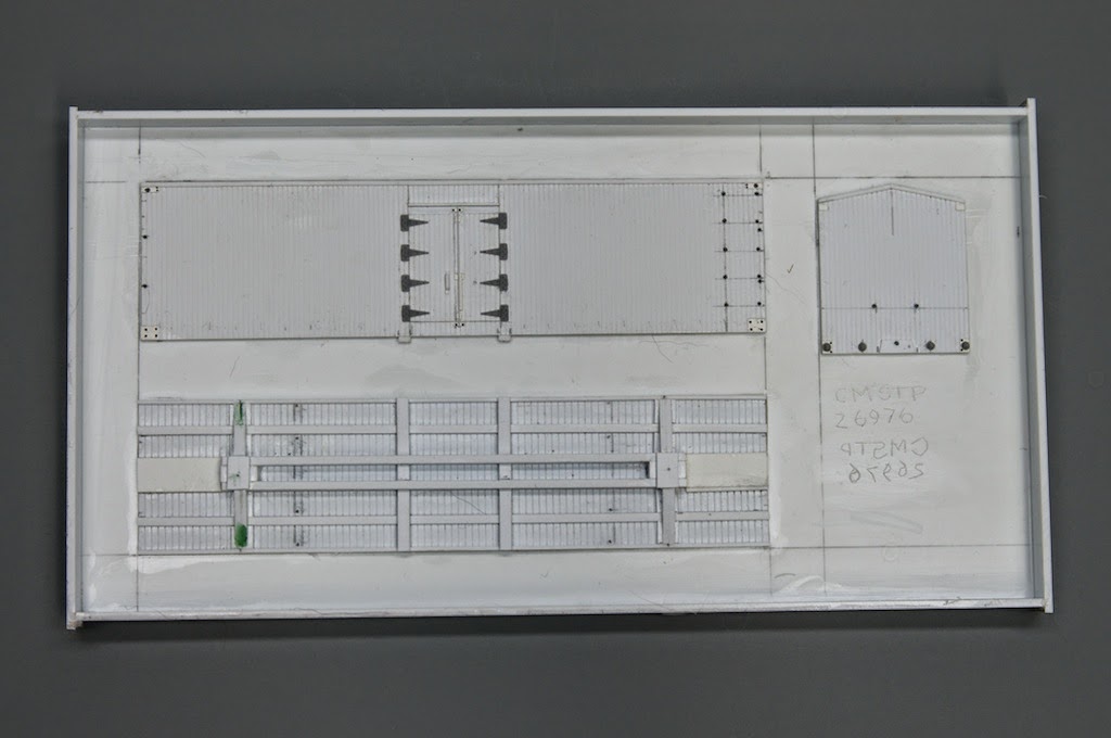
The starting point in the construction of this model is in creating a pattern for the underframe, side and end of the car. The pattern is fabricated using styrene materials. It may seem like extra work to create patterns to build a single model. Since the sides and ends are identical I find that I can spend my time getting the parts correctly detailed once and then cast the pair of parts. If I happen to want to create a second model it is a quick process to cast up additional parts.
This is the mold taken from the patterns. I use Smooth-On Mold Max 20 for the mold. It is mixed by weight (10:1) and has an overnight cure. The mold picks up all of the detail and is very durable.
These are the parts taken from the mold. I use Smooth-On Task 4 resin for the parts. I add a very small amount of brown tint to the resin to create a tan color casting. Task 4 is mixed by weight (10:1), has a pot life of about 45 minutes and cures solid in 16 hours. I find that the surfaces of my casting will have small bubble marks. I have not resolved this issue. I fill the holes with green putty, after painting they blend into the surface.
I purchased a pressure casting chamber and am now producing bubble/blemish free castings. Every detail is faithfully reproduced.
April 13, 2014
Building this model requires the creation of a square box from the sides and ends. When I cast the parts I attempt to fill the mold flush with the face. Usually they end up slightly overfilled so some effort is required to return the mating surfaces to there .040 thickness.
These are the backs of the castings after their edges have been worked back to proper thickness. I only sanded the mating surfaces, not the entire piece.
The sides overlap the ends. Assemble one side and one end. Take time to align the parts and make sure that they are square.
This is a closer view of the alignment of the end.
Next combine the two sub-assemblies into the completed car body. For all resin-resin bonds I use CA.
April 15, 2014
The sides of the floor required sanding to allow the end to fit between the sides.
This end fit between the sides without adjustment.
Align the needle beams that are cast onto the floor with their ends which are cast as part of the sides.
While maintaining the needle beam alignment mark the ends of the floor which overlaps the car body end.
Do the same with the other end. Remove the floor and cut off at the marks.
Fit the floor into the car body. Make sure that the coupler pocket pads are even with the bottom of the car body ends. CA the floor to the body.
When I created the pattern I added small dimples at the locations where the truss rods will penetrate the floor. In this view they are seven boards above the bolster.
Using these dimples as guides I draw a line across each of the needle beams. Next I use a sharp punch to mark the center of the beam at each line. Once done I drill holes for the pin on the Grandt line queen posts, in this case 10" posts. I like to use the Grandt posts as the pin provides extra strength. Finally CA the posts in place.
Drill through the floor at each of the dimples. Use thin mono filament fish line for the truss rods. Tie a knot, pass it through the floor. Thread on a Grandt turnbuckle, pass the line over one post and next to its corresponding post on the other beam. Pass the line back into the car body and out through the adjacent hole. Add another turnbuckle and continue the process until all four rods are completed. Use CA to bond the line in each hole.
This photo shows the completed stringing. In the back you can see two of the lines pulled up onto the second queen post. By only passing over one post you can snug up the line with less chance of snapping off the queen post. When you pull the line up over the second post you get nice taught rods.
April 21, 2014
The prototype bolsters on this car are fabricated from steel stock. I created the floor casting with the bolster in place. It only requires the addition of a cover plate. I fabricated this from styrene strip (.010 x .080). A slight bend is made in the strip where it extends over the side sheathing. I apply two Tichy .025 rivets on the end of the strip.
I use Titchy K brake castings on the model. I added a .020 x .040 strip under the air reservoir and a .020 x .080 strip under the cylinder. This assembly was then added to the underframe.
Next add the levers. Drill the holes for the lever hangers.
B end brake rigging. I use .0125 Tichy wire for all rodding and hangers. I angle the rods toward the car center to provide room for the swing of the trucks. Note the rivets on the ends of the bolster covers.
This is the "A" end of the brake rigging.
There was a slight discrepancy it the top right corner of the end casting. I filled the area with a .020 x .060 styrene strip and then sanded the pitch of the roof until it was flush.
Next I added .040 lead sheet to the floor to bring the weight up to 4 oz. I bond it in place with epoxy.
The sheet is purchased from McMaster-Carr in Chicago, part 9032K111 at $19 per 12" x 12" sheet. To protect the rodding and brake rigging add your trucks now.
The prototype car had a metal sheathed roof. I use .020 thick plane styrene as the base for the roof. Cut the sheet so that the length just overhangs the end of the car and the width just overhangs the sides. The exact measurements will depend upon the finished car body and can vary slightly so it is best to measure. I cut a few scale 3" wide strips from a .005 styrene sheet to replicate the metal seams. They are spaced about 21" apart and bonded with MEK. I use a very fine sanding film to burnish the top of the roof and seams, this will round over the sharp edges.
Split the roof and then draw a line 12" from the roof center seam, this marks the outer edge of the running board supports. Bond 18" long scale 2x4 pieces to the top of each seam strip. Add a running board support at the very end of each roof section as well (not shown in photo).
Castings now include fabricated roof.
Bond a .010 x .010 square styrene strip to the underside of the roof along the roof center line. Make sure that it fits inside the car body ends, it does not extend to the end of the roof.
Hold the roof on a flat surface and sand the ridge side of the roof. Work carefully to avoid pulling off the running board supports. Sand the edge until the .010 sq strip has been tapered.
When the sanding is completed you should be able to butt the ridges together. When the halves fit together and there is a proper overhang on the car, bond the halves together.
Bond the roof to the car body with CA. I use two scale 2x8's and one scale 2x6 for the running board. Start by bonding the center board with MEK and then bond the outer 2x8's leaving a slight gap between boards. Bond two .020 x .030 strips on the end to support the end platform, repeat on the opposite end.
The end platform is built up from scale 2x8's and a 2x4. Add a pair of Grandt NBW castings to the top where the grab iron will go.
April 22, 2014
Drill holes under each NBW for the ladders and grab irons. I use .010 wire so a #80 drill works. I form a bending jig from some scrap .040 thick material, drill one hole spaced appropriately from the end. Make an initial bend in the wire, place the bent end in the hole and then bend the wire over the end of the strip. Remove the grab and square up the bends then cut of the part.
Align, drill and CA Titchy steps to the side of the car aligned with the side ladders.
Assemble the brake step. Cut off the brackets trimming off the tiny alignment pins on the ends. Now attach them to the underside of the step before removing the step from the sprue.
Add the brake shaft step to the base of the car end. Now add the retainer valve near the roof eve and bend up some .008 wire for the pipe. Cut a shaft a little longer than needed add the brake step and use the shaft to align the brake step above the shaft step. Bond the brake step in place with CA. Do not add the brake wheel and shaft at this time.
Drill two holes on the car ends for the cut lever eye loops. CA a Tichy eye to the outer hole.
Bend the cut lever to shape. Thread it through the attached loop. Now thread the next loop onto the cut lever and place the loop tail into the center hole. CA in place.
Flip the car on its roof and add a .020 x .080 styrene strip next to each coupler pocket base. This is the attachment for the air line.
Assemble a pair of Cal Scale air hoses. Use your thumb nail and finger to add a curve to the hose, bond the hose to the bracket, angle it at 30 degrees from vertical. When set bond the bracket assembly to the pad on the car bottom.
The final step is to CA the shaft in place. Now CA the brake wheel in place and trim off the excess shaft. At this point the car is ready for painting.
May 5, 2014
I used Scalecoat II paint for this model. I like this paint as it is gloss and is ready for decal application when dry. I painted the roof and ends Boxcar Red 2. The ends of the car may have been yellow as the decals had black end reporting marks and of course I didn't notice that until the painting was done. The photo that I used for reference did not show the end so, for better or worse, mine happen to be red and have white reporting marks.
Mask off the roof and ends and paint the entire side white, I had only painted the area of the circle white and the white patch showed through when I painted on the yellow. I had to stop with the yellow and repaint the entire side white, I guess I should have known better. Always relearning something!
I am using Art Griffin decals on this model. These are ultra thin decals so you need to work carefully with them. As printed the decal spacing fits the car side, you only need to separate major components. As can be seen above there are four components.
This photo shows the film floating free from the backing. Use tweezers to grab the backer, reposition under decal and lift the film out of the water. This is a little tricky as surface tension will make the decal float away from the backer. You want to insure that the entire film is on the backing without over hanging the edges.
Wet the car side with water, position decal and slip the backer from behind. This is also a little fussy to do but just take your time. The decal film should be floating on a layer of water and can be repositioned by gentle nudging with a brush. If things are not going right add water, slide the backer behind the film and start over, you may even need to put it back in the soaking dish and start over. Just remember to be gentle with the film.
Now use a brush to work out the excess water from behind the decal. I brush from the top to the bottom and wick out the excess water from along the bottom of the decal with the brush.
This is how the freshly applied decal film appears after the water has been drawn away. Finish applying the other decal sections. Now comes the hard part. Leave everything ALONE and allow the film to dry at least overnight.
This is how the decal looks after drying. Note that it has virtually melted into the paint surface. To really fix the film I apply several coats of Walthers Solvaset allowing the film to completely dry between applications. I then use a new razor and lightly slice down each board and apply more Solvaset. Allow the model to dry for a few days and then gloss coat the entire car. When dry I brush paint the under carriage black.


No comments:
Post a Comment