Wednesday March 20, 2013
The plan for this pump house comes from the July 1986 Mainline Modeler, it is a Wabash standard plan. The building is built with board and batten construction and will match the style of the engine house. I am sure that the drawings in MM are copyrighted and I am not going to photograph the page and post it. I will provide prototype dimensions where appropriate. I use a mm dial caliper to aid in my model building so you will see many dimensions in mm. It seems easier to measure a dimension in mm than in feet and inches. 53 mm is much simpler to measure than 15' 3".
This is a side wall. The prototype drawing has a note that if the building contains a locomotive style boiler it is 30' in length. I am building the as drawn 20' building.
This is the layout for the windows. I am using Tichy Train Group #8153 windows, the wall opening is 10 x 20.5 mm.
I chose to overlap the sides with the ends on this model. Usually I do it the other way around but the shallow pitch of this roof reduces the gap that is produced at the wall-end junction. The above dimensions reflect the reduction in width for the inside fit, the prototype width is 16 feet. This side is 53 mm wide and 49 mm tall. One end of the building has a single door. I am using a Tichy #8049 four panel door, opening 23.5 x 11 mm. There is a scale 1x8 (2.5mm) trim board around the bottom of the walls, the height of the door opening includes this.
This is the opposite end, it has a double door. I used a Grandt 5073 door casting, opening 28.5 x 22 mm. The center of the peak is 26.5 mm from the side.
This photo shows how I lay out the roof edge on the end. I prop up the side wall and then use my straight edge draw a line from side to peak.
I use a #17 X-acto blade to punch through the side wall along the bottom of the window opening. When you have a narrow side, as is seen on the top of the window (right), I provide a relief space by bevel cutting an opening in the window bottom. I then cut the window sides free. Last, I punch through the window top. As the blade cuts through the wood the scrap material has room to move down toward the notch preventing the splitting of the narrow top piece. For illustrative purposes I have worked from the back of the wood, it is much better to work from the face of the material.
Here are the four sides.
Thursday March 21, 2013
These are the steps taken to modify the windows. From left to right. Unmodified window. Remove protruding corners on upper trim board. Back view, cut off sill trim to match interior casting frame. Finished window, frame textured by scrapping with razor saw blade.
Double door modification. Cut off the transom.
Remove the corner of the side trim at the top of the door. This will allow the top trim board to sit flat on the top edge of the door. Left side marked, right side removed.
Add a scale 1x4 to the top of the door. Again texture the frame with the saw blade.
The plastic parts are primed with Polly Scale D&H Gray.
Remove the battens from the bottom of each wall. This is for the scale 1x8 trim board. Scribe across the work piece and then shave off the batten up to the scribe line.
I use substantial bracing on my models. In this case 1/4" sq wood in the corners, along the wall bottoms and the side tops. I used 1/8" sq on the gable edges.
This is a half roof section showing the dimensions. The prototype had 12' overhangs on all sides.
I use CA on the 1/8" sq. gable strips and carpenters glue on the side wall edge. If some of the carpenters glue squeezes out it can be cleaned up with water in a small paint brush. The surface can still be stained and painted if it is cleaned up promptly. CA will seal the surface so be careful when using it.
When the glue holding the roof sections is dry I sand the side edges. This produces a taper on the edge. I also sand the ends to make sure they are square.
This is what the completed assemble looks like.
Friday March 22, 2013
I stained the walls with Dr.Ben's weathering solutions. Once dry I applied washes of diluted Model Flex Light Maroon Tuscan Red. I also added the 1x8 base trim and the 1x6 roof trim once the building was painted.
The battens will need to be removed from under the trim on the doors and windows. Place the casting in the opening and use a sharp blade to scribe through the battens using the trim as a guide.
Again with a sharp blade shave off the battens.
I primed the castings with Polly Scale D&H Gray.
I then stained them with the same paint used on the walls. Once the paint was dry I glazed the windows with clear styrene. I use Future floor wax to bond the styrene to the castings. When the glazing was dry I bonded all of the castings to the wall openings. A little CA applied around the opening from the inside makes quick clean work of this.
Saturday March 23, 2013
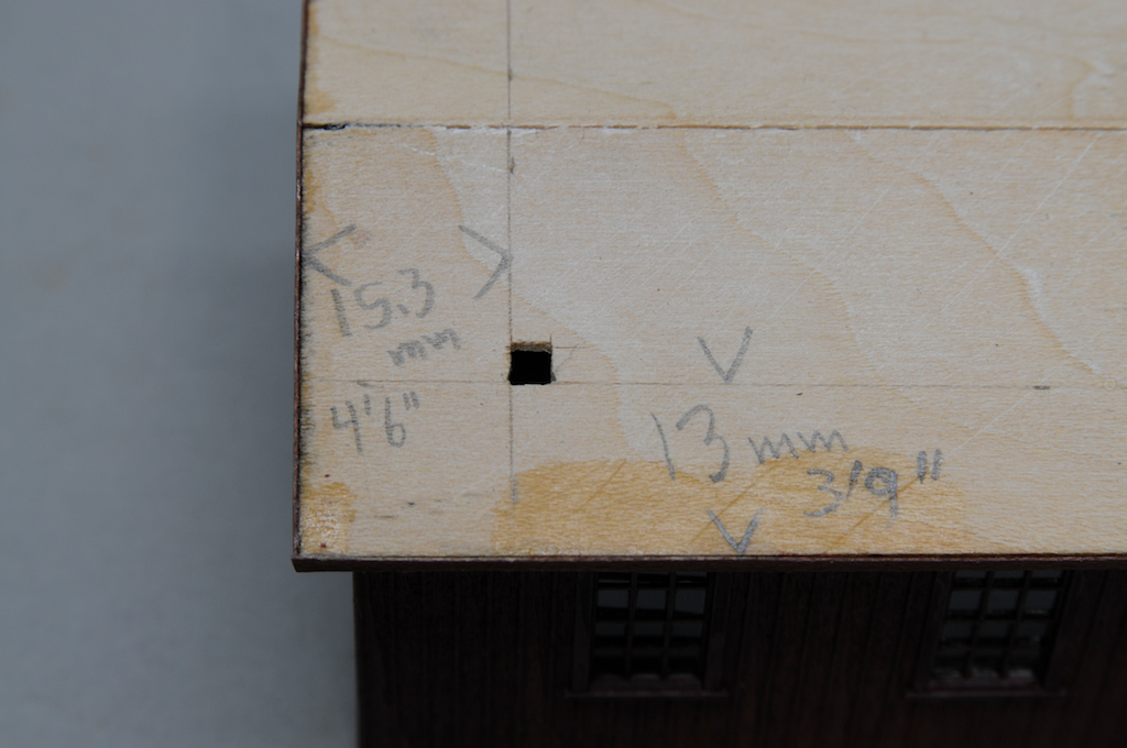
The pump house has a head frame positioned over the well head. It is built up from scale 8x8 timbers. The above photo shows the dimensions that locate the hole through the roof. There is another directly opposite this one.
This is a view of the assembled frame. The top piece is a scale six feet and the sides are sixteen feet above the roof.
This view shows how the frame post extends to and rests on the 1/4" sq base. It was necessary to file a notch in the upper wall 1/4" sq strip to clear the head frame post.
When ever I build a timber framing, such as that seen on the coal loading derrick, I use mortise and tenon construction. I produces a exceptionally strong joint and is worth the effort.
The tenon will be six scale inches in length. For this assembly the top will need to be tapered I estimated that there is a three inch slope between sides. I needed to adjust this a bit flatter during final fitting.
I formed a cutting base from scale 6x8 strips. The depth of cut on each side of the 8x8 will be two scale inches. This creates a tenon four inches square. Press the blade into the wood until it hits the styrene strips.
Slide your blade into the end of the strip wood to remove the scrap material. Rotate the wood and repeat the process on each side.
Here is the completed tenon.
To create the mortise I drill a hole in the wood using a drill which matches the size of the tenon. In this case the hole is angled. For a large tenon it is necessary to round over the corners, square peg in a round hole problem.
Sunday March 24, 2012
One of the timbers on the head frame has climbing irons. I bent these out of .008 brass wire. They are spaced 18" apart and are staggered, extending about 6" from the side.
Normal number drills do not go down to .008. I fabricated my own drill by cutting off a small piece of the wire making sure that there was a flat crushed end. With a light touch it will drill into wood effectively.
There is a steam boiler in the building to provide power to the water pump. To create a stack I drilled a 1/8" hole in the roof and enlarged it with a file until a 1/4" styrene tube could fit. I tapered the top edge and CA'd it in place.
I next bonded a 3/16" styrene tube into the 1/4" tube. It extends about five scale feet above the roof.
Prior to shingling the roof I drew 1/4" grid lines to aid in positioning the shingle strips.
I used American Model Builders Shake Shingles #335 for the roofing. I initially stain the sheets with DrBens IA, WR and Driftwood stains.
Monday March 25, 2013
Smoke Jack Top. I used a paper punch to cut out a circle of .002 brass sheet. I then cut in from the edge to the center and pushed the metal together to form a cone. In this photo the tweezers are holding the cut edges together. I soldered the joint and then did final shaping of the cone.
The standoffs are made from .010x.018 brass strip bent into an "L". The bend made in this strip is very brittle so you cannot re-bend it in any way, it will brake. (Perhaps heating the strip to red hot would anneal it and reduce the brittleness). I then soldered the bent strips to the cap positioning them a little way back from the edge and 180 degrees apart. The standoffs are then cemented into the interior of the smoke stack.

Add stained 1x8 strips to the peak as a cap. I apply washes of Van Dyke Brown and Black to the shingles to enhance the variegation in there color. I use artists oil colors thinned with mineral spirits. The mineral spirits softens the shingle adhesive allowing me to lift individual shingles, improving the aged appearance of the roof. A 3/64 styrene rod was used to represent the steam engine exhaust. A couple of NBW were added to the top of the head frame. When the roof was dry I painted the chimney and exhaust Polly Scale Grimy Black. To represent tar around all of the roof penetrations I added a small amount of black acrylic paint. Final weathering includes soot on the chimney, white on the steam exhaust and a wash of Weathered Rust on the buildings sides.
Here is the boiler side of the finished model.


No comments:
Post a Comment